
PLC SYSTEM
PLC system The PLC control system and its control technology have been gradually promoted and applied in the flour processing industry in recent years. Relying on its own advantages, DTC has established an automation research institute and has a professional complete set of PLC control system research and development team. The PLC control system developed by our company has been widely used in large and medium-sized flour processing enterprises and has achieved good market results. DTC PLC control system can realize the whole process management of visualization, dynamic, data informatization, standardized management process, and paperless operation documents of the whole processing process.
- Description
Description
PLC system The PLC control system and its control technology have been gradually promoted and applied in the flour processing industry in recent years. Relying on its own advantages, DTC has established an automation research institute and has a professional complete set of PLC control system research and development team. The PLC control system developed by our company has been widely used in large and medium-sized flour processing enterprises and has achieved good market results. DTC PLC control system can realize the whole process management of visualization, dynamic, data informatization, standardized management process, and paperless operation documents of the whole processing process.
PLC system
PLC system
FEATURES
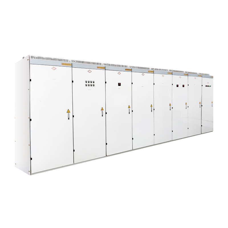
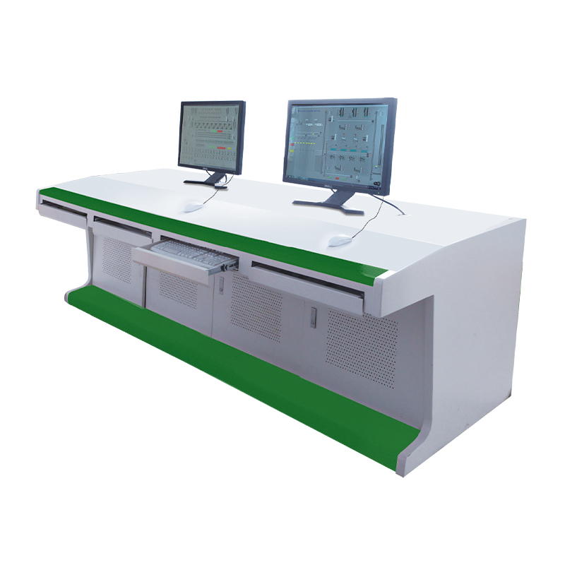
Control system composition:
The control system consists of monitoring computer (host computer), programmable logic controller (PLC), switch, motor control center (MCC), field operation box, field junction box, field sensors and other major equipment.
PLC System Functions:
System functions include monitoring functions, operation functions and fault alarm functions.
Monitoring function: The graphic operation interface of the control system has the function of displaying process flow, all the equipments involved and the states need to be displayed are displayed in the system. On the color display in control room, the manual/automatic status, running status, fault status, gate valve position, speed of conveying equipment, process operation, etc. of all controlled equipment can be monitored.
Operation function: The upper monitoring system also has the control operation function, replacing traditional console button operation. The upper monitoring system provides a set of color graphics display system in the menu mode, and selects a desired window screen through the mouse operation menu. Process selection, confirmation, start, stop, setting of workload, input of varieties, and centralized start and stop of a single machine can all realize “one-button” operation.
Fault alarm function: When the field equipment fails, the monitoring system can prompt the computer screen in the form of sound and light alarm, and display the alarm information, automatically pop up the alarm window, display the cause of the fault, and automatically record it in the fault report. The equipment failure time, failure name, troubleshooting time, failure cause, failure confirmation information and operator are automatically recorded in the equipment failure table, which can be viewed and printed.
System control method
There are three modes of operation of the control equipment, namely the selection control of the on-site operation box, the control of the MCC cabinet, and the soft manual “one-key” automatic control of the PLC .
On-site operation box selection control: On-site manual control is used as an auxiliary control method, which is completed through the on-site operation box next to the field equipment. This method is suitable for mechanical equipment commissioning, mechanical maintenance and when central control room is not remotely controlled.
Control room MCC cabinet control: When the on-site control box selects the “remote” switch, it is operated by the selector switch and the start-stop button on the MCC cabinet door of the power control room. The selector switch is set to three gears: manual, stop and automatic. The start and stop buttons on the cabinet door manually control the working state, and can control the start and stop of a series of related equipment in the corresponding area; when it is adjusted to “stop”, the equipment is in a stopped state; when it is adjusted to “automatic”, the equipment is controlled by a PLC system.
Central control room PLC soft manual and “one-button” automatic control: When the knob on the MCC cabinet is set to “automatic”, and the transfer switch on the on-site operation box of the relevant equipment is in the “remote” position, the PLC will issue a control command. In this control mode, the related equipment in the process has an interlocking relationship.
According to the operation flow of the production process, the production order of a certain batch is used as the control record traceability unit, and the production scheduling plan can be issued from the MES system to the control system. After choosing to execute “one-button” control, the automatic control system automatically executes all operations of a certain process according to the production process.
SYSTEM APPLICATIONS:
Our company is committed to MCC cabinets, PLC cabinets, socket boxes/maintenance power boxes, low-voltage power distribution cabinets, solenoid valve control cabinets, junction boxes/motor control boxes, junction boxes/transfer boxes, automatic control operating systems, automatic control system host computer interface and other services, We can undertake automated production lines in flour, grains, brewing, packaging, weighing and related fields, non-standard automation design, manufacture, installation and debugging of stand-alone products.